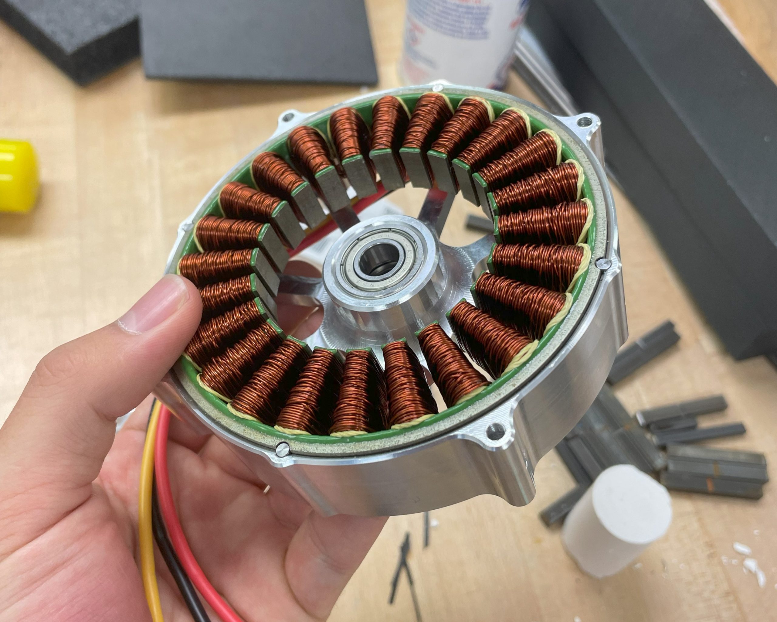
Ever since I learned about the work that Ben Katz and JPieper were doing (among many many others) I have wanted to make my own BLDC motors. As such, for my honors thesis, I decided I would make a few! And before anyone asks, no, I did not wind them myself. This project focused on the mechanical design of the motors, but I’d like to take a stab at different windings in the future. This is a follow-up to my previous post where I developed math to describe a five-bar robot. These motors were for this robot, and I used them to get it to move (very quickly)!
BLDC Motor Concept Generation
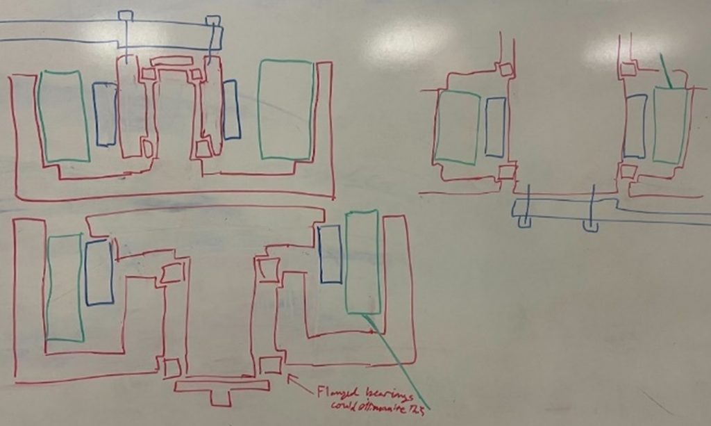
Like all good projects, this one started off with a series of poorly drawn cross sections. After a long day of lab supervising, I worked with another one of my coworkers to come up with a few ideas for how I could design one of these motors. I eventually decided on the bottom left design because it could be manufactured with less parts and gave better options for mounting something to the shaft of the motor.
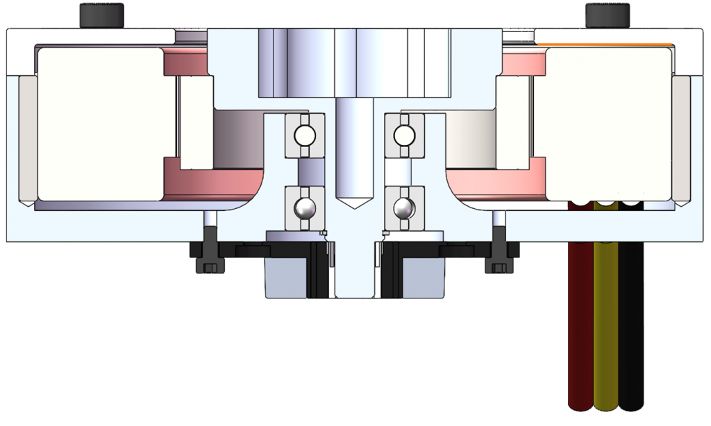
Eventually I graduated to a proper CAD cross section of the BLDC motor. This took some time of course, but I’m very happy with the results. I used pins along the edge to solidify the stator, and used a partial press fit to mount the rotor. This made it much easier than press fitting along the entire length and prevented unnecessary undercuts. This allowed the part to be easily manufactured with lathing. One thing I am unhappy with about the design is the relative location of the bearings with respect to each other. I would have preferred them be farther apart; however, this allowed the shell to be comprised of only one large billet, allowing the relative tolerances to be tighter.
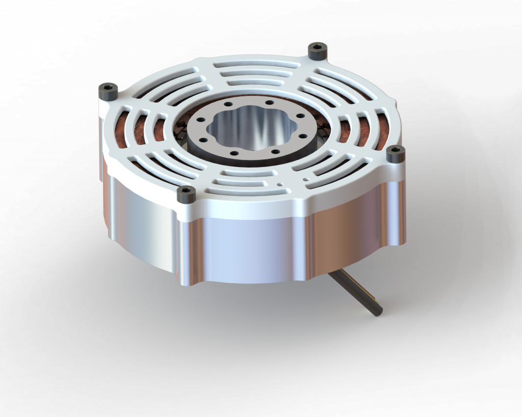
I also made a full render of the motor. As you might notice, there is a small spline integrated into the motor hub which may be used in future projects for locating different attachments. This was milled in after the lathing operations along with the screw holes.
Machining the BLDC Motor Parts
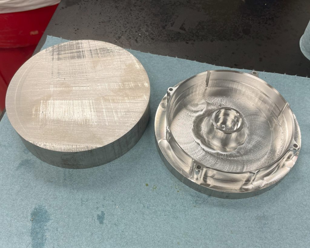
At this point we were ready to generate CAM and actually use a CNC machine to create the parts. I started with 5 inch aluminum stock for the stator and a 2 inch aluminum stock for the rotor.
After I had machined that portion, I just had to do the same thing twice! I also ended up doing most the the rotors in the CNC machine too to save time.
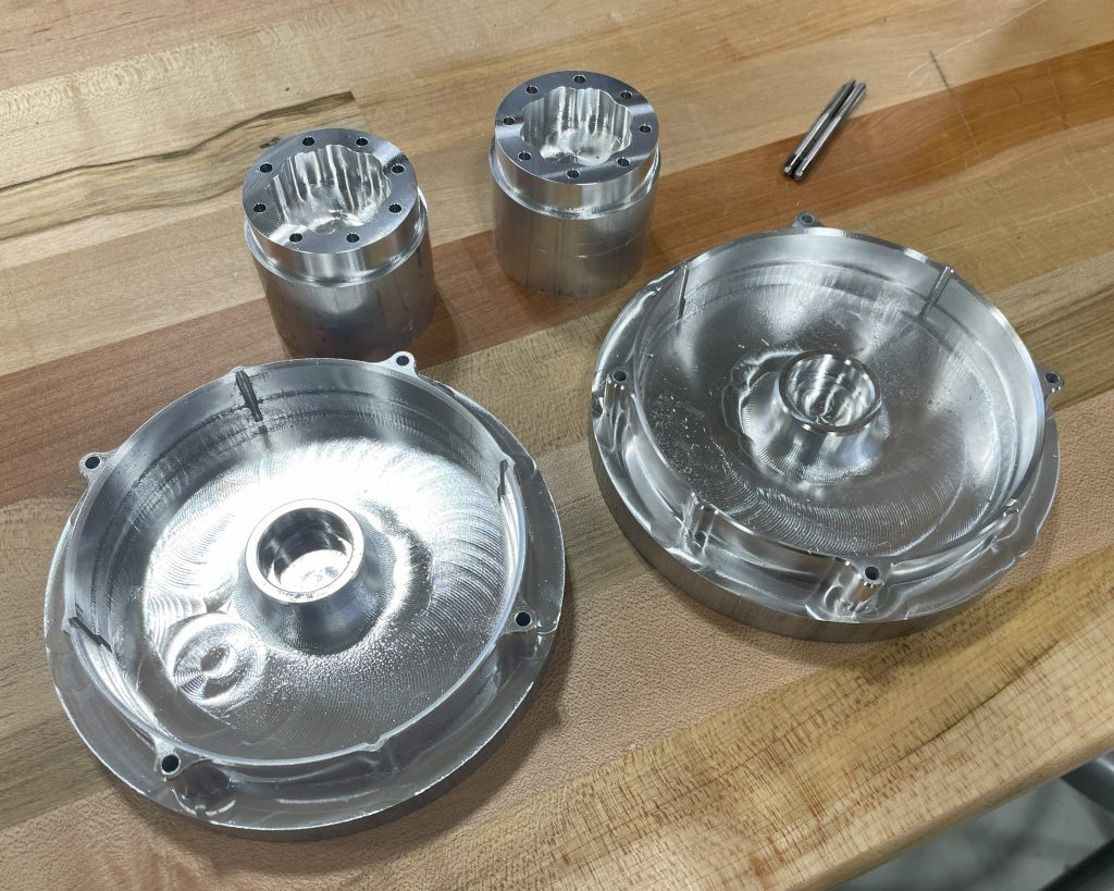
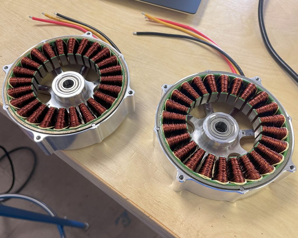
Finally, we just had to machine the other sides of each of those parts! This gave me 4 parts (miraculously with nearly no errors) and this was enough to build the two motors.
Assembly of the Motors
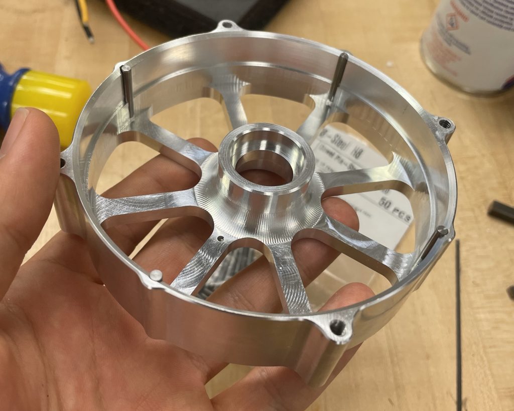
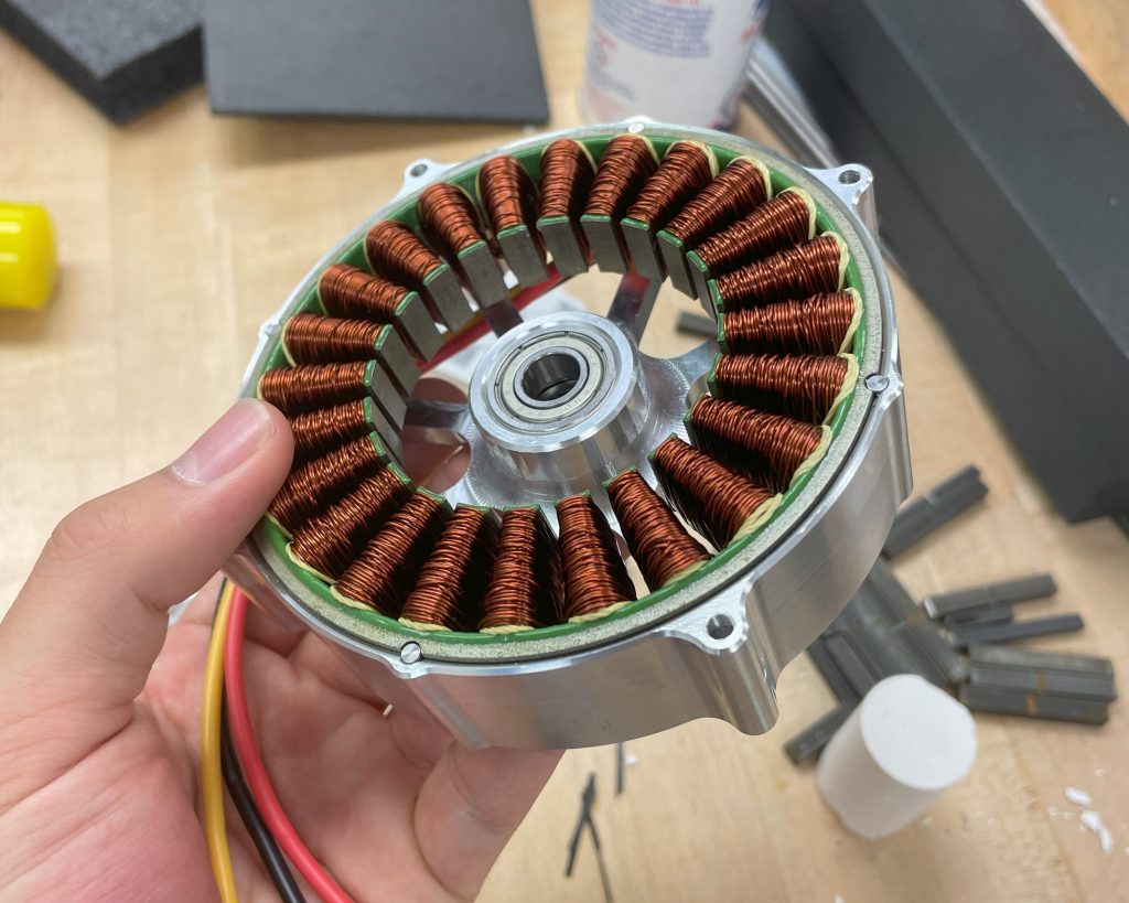
After I had machined everything, I just had to add all of the parts. This involved inserting the stators, which was a matter of a light press fit and alignment with the pins. I had to be very careful not to damage the coils, and I used something to press along the rim to avoid causing that damage.
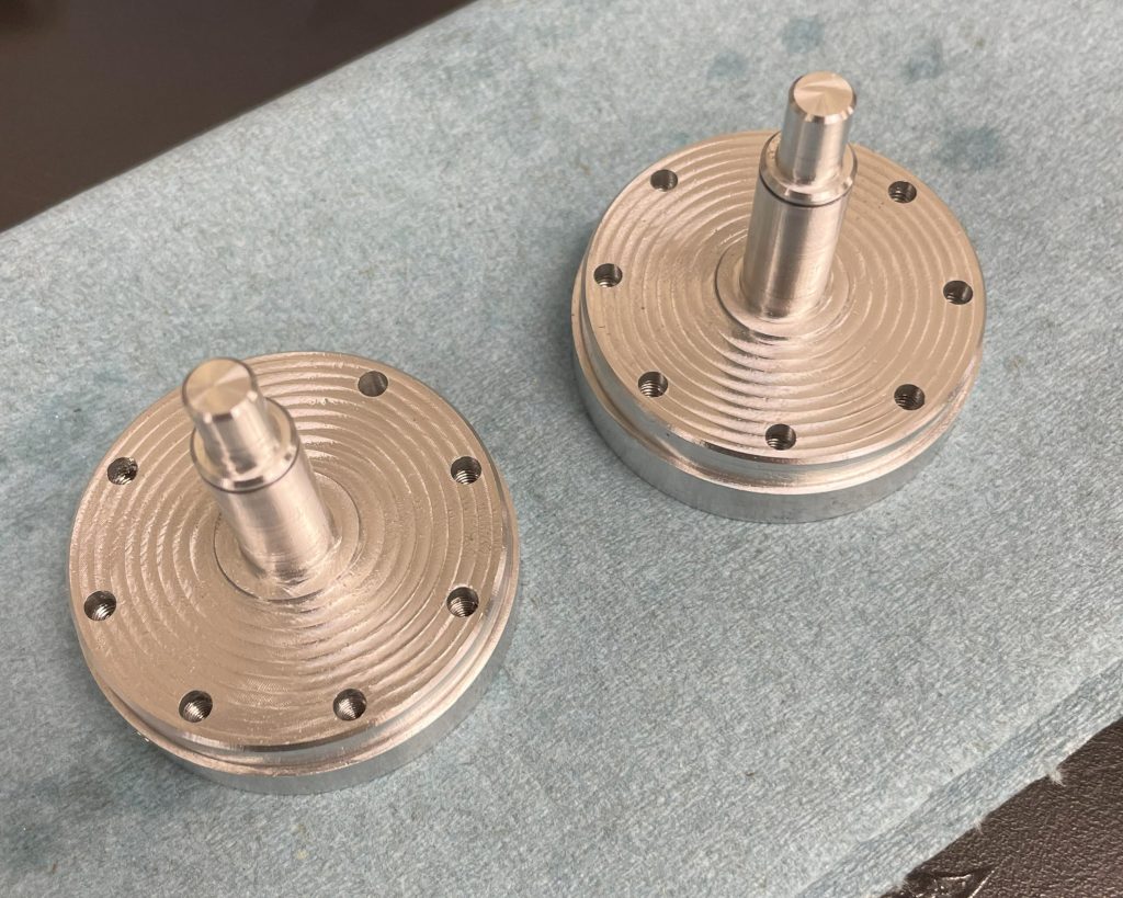
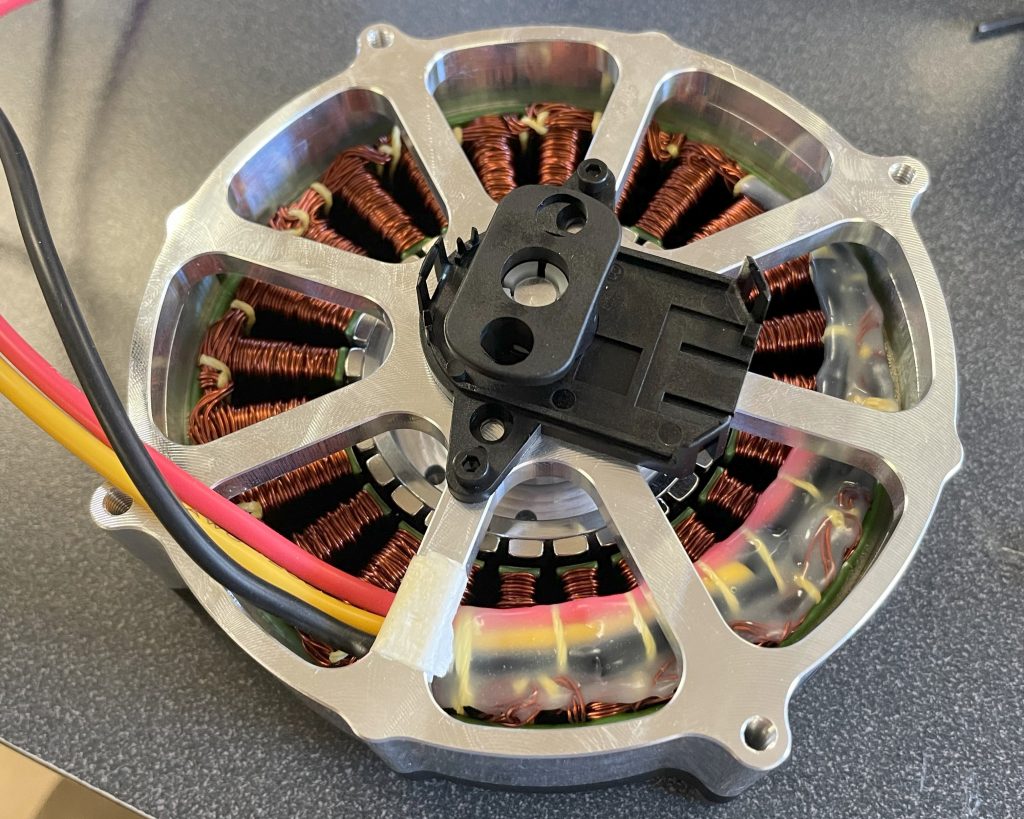
Unfortunately, I forgot to get pictures of press fitting the rotor magnets onto the rotor shafts, but that was the next step. This step was the most stressful and had the highest likelihood of wrecking parts. Fortunately, cooling the aluminum in the fridge and warming the magnet (only a little as to not damage them) made the press fit work perfectly. In addition to this, I noticed that my rotor shafts were a tad loose. This was no issue though, and I applied some Loctite between the shafts and the bearings. This will make disassembly hard, but that’s a problem for future me as I didn’t have enough time to re-machine those shafts and buy new rotor magnets. After this, I could put the encoders on the device.
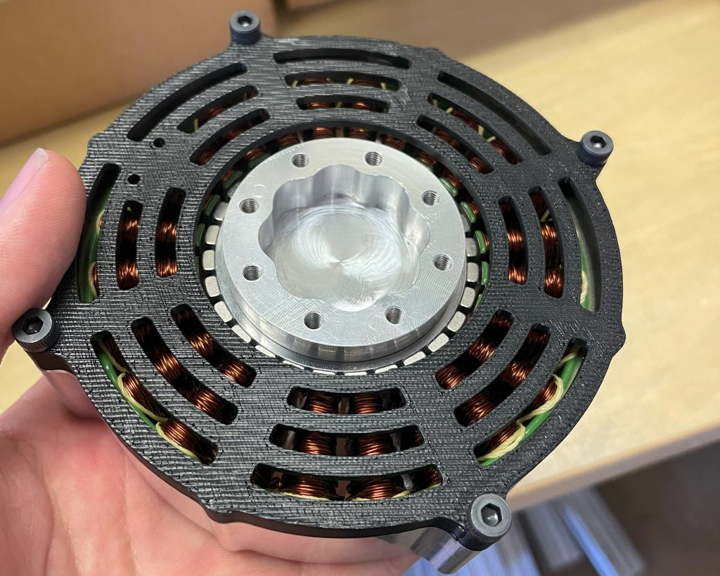
After I installed the encoder and the 3D printed stator wire shield, I was finished! I would definitely do a few things differently given another chance, but here is the final picture of one of them.
Summary and Future Ideas
These motors were built to deliver lots of torque, and they held well up to that task. However, I think if I were to rewind them, I’d be able to make better use of that. The stators I purchased were 100kv, which while low, was not low enough for the low speed regime I wanted to run the motors in. I think I could have gotten a lot more performance out of them if I had spent that time, but they were good enough for my application playing air hockey. In the next post I’ll cover the build of the air hockey robot and some more about the programming involved.
One thought to “From Design to Reality: BLDC Direct Drive Motors”