Don’t we love it when a project wraps up? This is one of those times where a project has been in the works forever and finally gets finished. Frank the differential drive robot (the name I’ve given him) is finally to a point where I can do just about anything! For this post I’ll cover what I did most recently with a custom remote controller and real time operating system (RTOS). However, I plan on adding some functionalities for position estimation as well as path planning using something like A* or rapidly-exploring random trees (RRT). Everything I’ve finished has been uploaded to my GitHub and I plan to add some user friendly features as I expand the python library I’m designing.
Getting the Radios Working
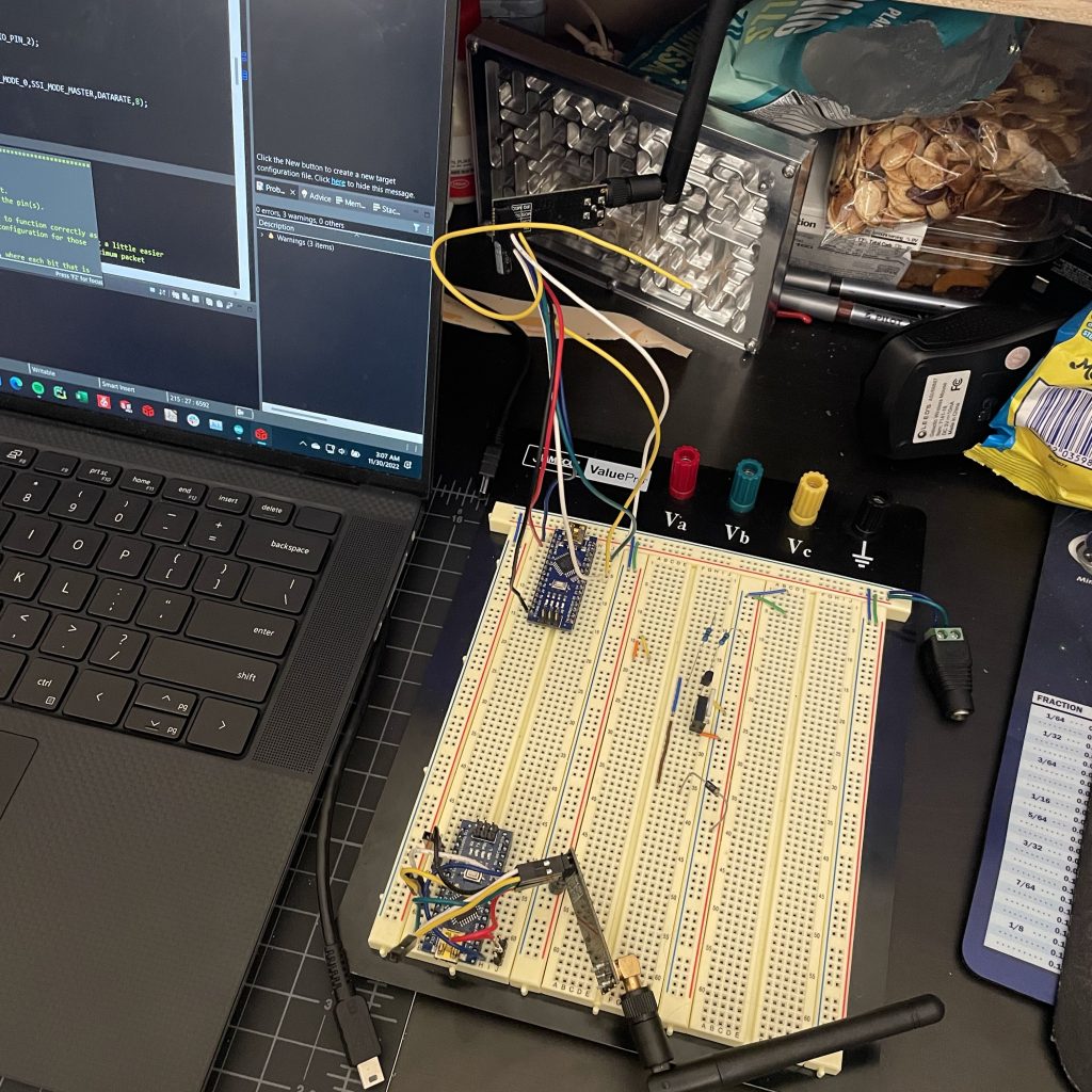
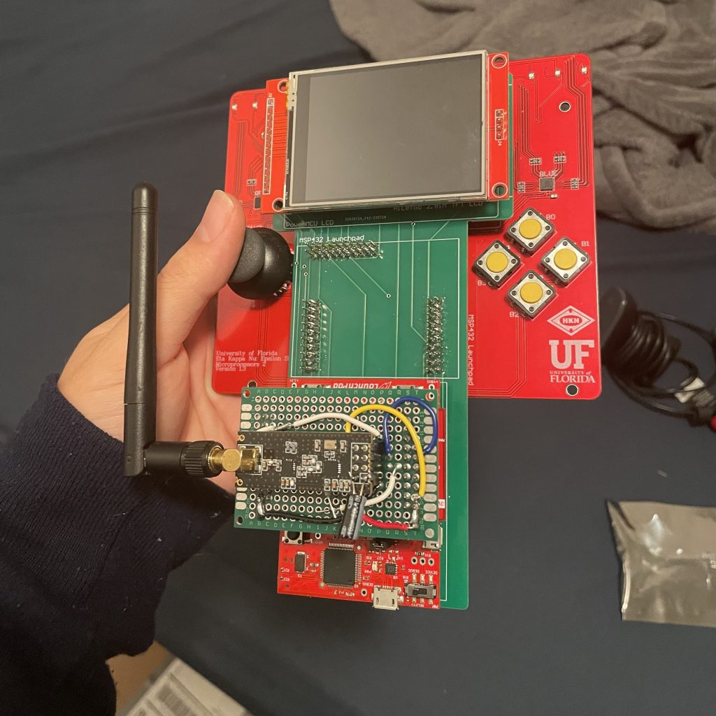
The first thing I did was get the two nrf24l01 RF radios communicating. This took awhile because I had to rewrite part of the driver for the TM4C123GH6PM processor on the Tiva Launchpad I was using. It was not ready to be used with the i2c port that I wanted to use, so I had to modify the driver for this. I then got the module working on the Raspberry Pi on Frank. This was using the RF24 library I found. This took some time as I had to build python bindings for their C++ library. Their provided instructions worked quite well though, so I definitely recommend this library for others in the future.
After I got that working I got the other modules working with their respective device. That included a servo hat and BNO055 IMU/gyro for the raspberry PI, and an LED controller and IMU/gyro for the Tiva. Luckily for me, I only had to write the driver for one of these, the LED controller on the supplemental Tiva board.
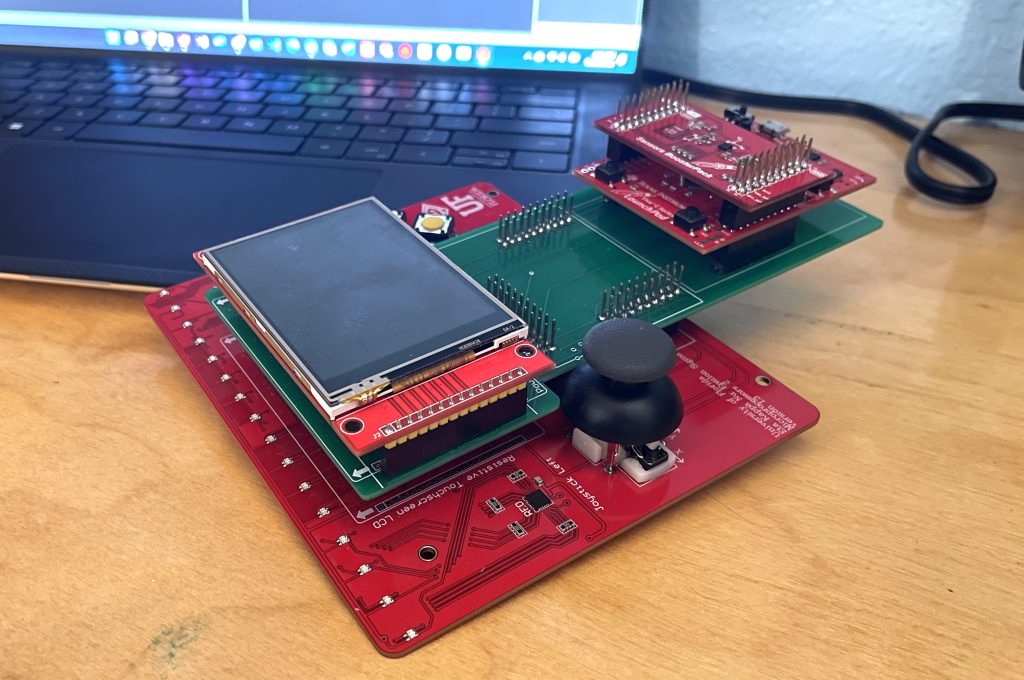
The Real Time Operating System and Remote Controller
After I got all of the hardware working, I starting writing code to combine them in different ways. This is where the RTOS concepts came in. For my Microprocessor Applications 2 (EEL 4745C) class I coded a custom RTOS in C on the Tiva Launchpad. The RTOS handled the generation of periodic, aperiodic, or background threads and had functions for sleeping, blocking/semaphores, and thread safe queues. For instance, I made two background threads, one for receiving and one for transmitting data from the Radio. I also used a thread safe queue to manage data access to the joystick and some of the incoming radio data.
I will not go into much more detail on the implementation as there was a lot of code specific to the processor I was using. However, I will say that I got an intimate understanding of stack manipulation as a result of the project. This was the source of most of my issues, so if you happen to be working on your own RTOS, definitely check the stack during debugging.
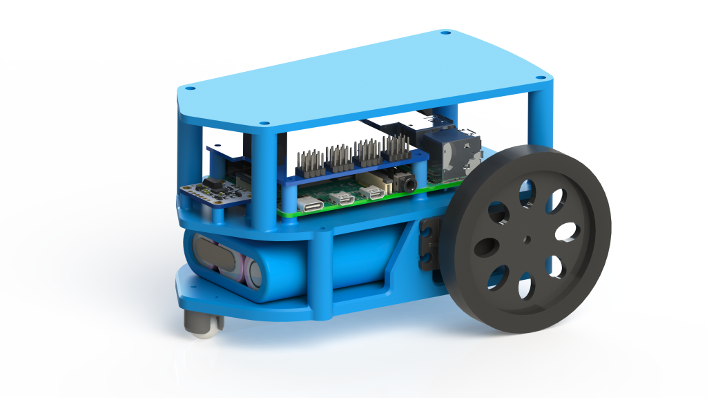
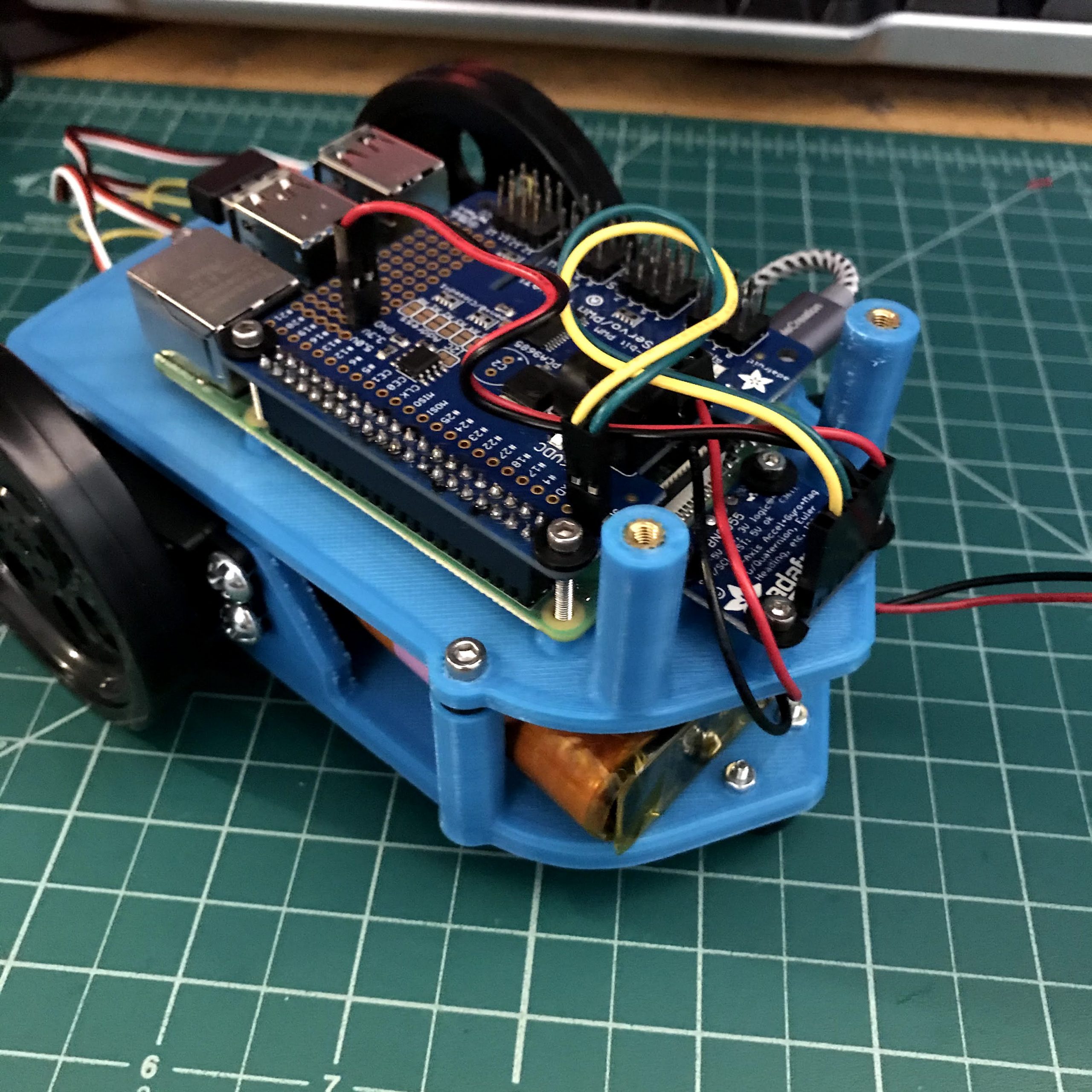
The Raspberry Pi Robot (Frank)
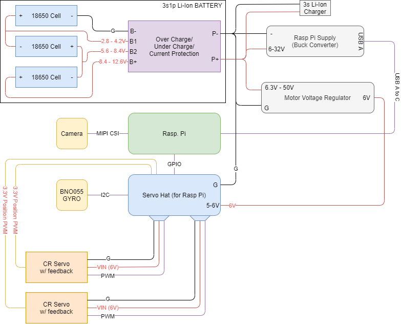
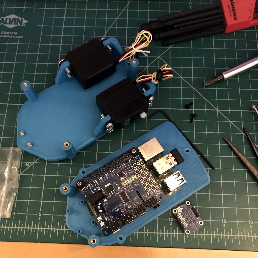
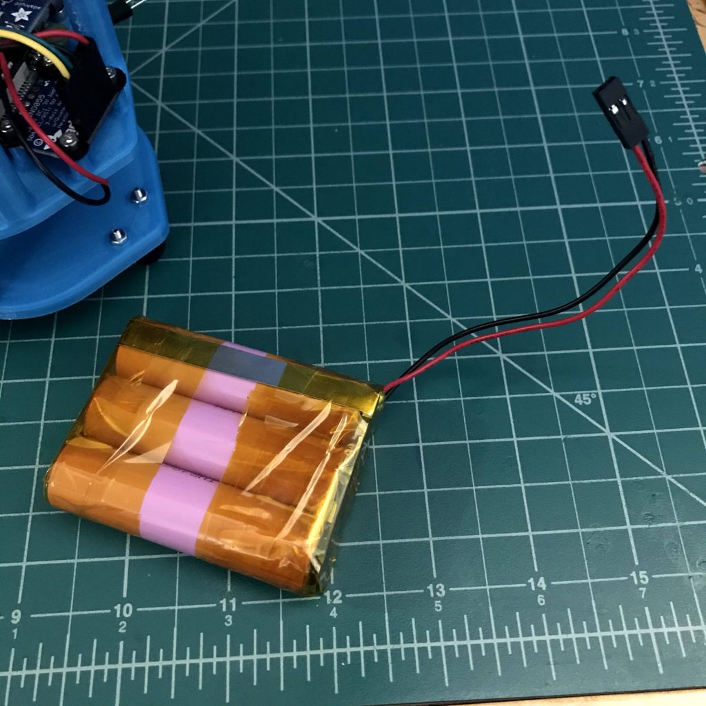
Frank only took a few days to design and print, and with shipping only taking about a week, this part of the project moved very quickly. Below I have included a wiring diagram and the some build pictures. I can provide a BOM or CAD if requested, but Frank cost approximately $300.
Programming Frank’s Motion Controls and Facial Tracking
The programming for Frank was a culmination of projects from class as well as concepts I learned on my own time. Fortunately, for the raspberry pi there was far less custom code. I was able to use the existing threading libraries to do everything. I had threads for each peripheral on Frank. Because the data was not used for anything high performance this worked well, but in the future I’ll probably have to synchronize these systems in some way for accurate control. This worked pretty well for motion controls from the Tiva board to Frank.
Frank can also do facial tracking! This was easy to implement but was a bit of trouble due to some of my python libraries being old or missing (I’m looking at you 2019 NumPy). After I got that fixed I was able to get it working! To track faces, I calculate the average face position in the image. I then offset this value by half the width of the image. This new value can be considered as the error that the robot has to correct for. It then figures out what to do using a PID controller. Due to the camera latency, it has some difficultly tracking, but with some small changes, specifically by adding angle estimation or some type of feedforward term, I’m sure I could improve performance.
My Frank Project Summary
I have learned so much throughout this project! I already felt comfortable with Python, but this has made me feel far more confident with C, so I’m really happy I did all of this. Additionally, combining my knowledge of electronics, mechanics, and programming to make a robot has been a really rewarding experience. I am definitely going to have to dive deeper into the programming and libraries I have been developing to make something more reusable. Looking forward to future development!
One thought to “Frank the Robot and Real Time Operating Systems”